TM 55-2350-224-14
Table 3–2. Continued
Item
Quantity
Description
Come-along or
1
Adequate strength cable tensioning device.
cable tightener
Blocking Materials
Lumber (nominal sizes)
Douglas fir, or comparable
2- x 4-in.
40 linear ft
Specification MM-L-75.
2- x 6-in.
12 linear ft
2- x 8-in.
12 linear ft
2- x 12-in.
12 linear ft
straight grain, free from material defects, Federal
Nails
Common, steel, flathead; bright or cement-coated, type II, style 10, Federal
12d
120
Specification FF-N-105.
30d
80
40d
10
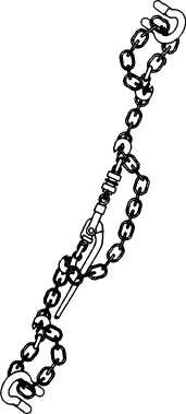
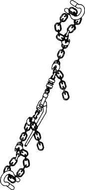
Option 1: 1 chain,
1 loadbinder
Figure 3–1. Detail of rail chain tiedown patterns.
b. Loading. Place the carriers in the tiedown
position on the railcar, using a crane of adequate
capacity (see para 4–5 for lifting guidance), or
drive the carriers onto the railcar if a suitable
ramp is available. Position the carrier so that
sufficient railcar tiedown points are available.
Carriers must face in the same direction, with a
minimum space of 10 inches between them and 6
inches between the brake wheel and the front of
Option 2: 2 chains,
1 loadbinder
(Table 3-2, chain assembly, option 1 and 2)
the carrier. Do not set handbrakes on the carriers.
Place gearshift levers in neutral. Total load re-
straint (para 1–4) is three times the carrier GVW
per AAR, Section 1, General Rules Governing the
Loading of Commodities On Open Top Cars.
c. Tiedowns and Blocking. Figures 3–2, 3–3, and
3–4 and table 3–3 provide instructions for restrain-
ing the carriers against forces encountered in
normal rail operations.
3-3