|
| |
TM 9-2350-287-20-2
12-2. STEERING CONTROL LINKAGE REPLACEMENT (continued).
f.
1.
2.
3.
4.
5.
6.
7.
ADJUSTMENT
NOTE
All adjustments to steering linkage must end with transmission steering control lever in
neutral position (pointer on steering shaft aimed at center position rnarker on transmission).
Steering wheel must return to neutral position (center spoke vertical).
Removable pins should insert easily through rod ends after adjustments are complete.
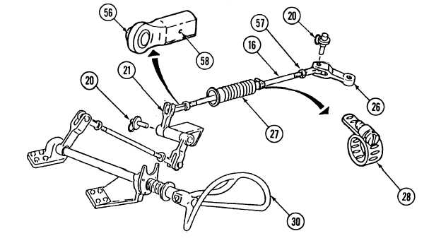
Turn steering wheel (30) full left and hold, Check for contact between rod (16) and bottom of passage hole
in bulkhead (hole where rubber dust boot is installed). If there is contact, go to step 2. If no contact, go to
step 7.
Remove two quick-release pins (20) from lever (21) and steering control lever (26). Loosen clamp (28) on
rod (16).
Loosen two nuts (57) on rod (16). Adjust both rod ends (56), and lengthen rod (16) as required to stop contact
between rod (16) and bottom of passage hole.
Tighten two nuts (57), and insert small wire into each witness hole (58) on rod end (56) to check whether
witness holes are closed after adjustment is complete.
Install rod (16) and two quick-release pins (20) on lever (21) and steering control lever (26).
With steering wheel (30) in neutral position (center spoke vertical), tighten clamp (28) while dust boot (27)
is not stretched or compressed. Tightened clamp should be approximately 5 1/2 inches from bulkhead.
Turn steering wheel (30) full right and hold. Check for contact between rod 16) and bottom of passage hole.
If there is contact, go to step 8. If no contact, go to step 10.
12-12
|