|
| |
TM 9-2350-287-20-2
12-2. STEERING CONTROL LINKAGE REPLACEMENT (continued).
8.
9.
10.
11.
12.
13.
Remove two quick-release pins (20) from lever (21) and steering control lever (26). Loosen clamp (28) on
rod (16).
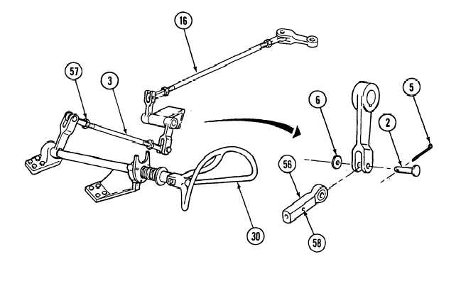
Loosen two nuts (57) on rod (1 6). Adjust both rod ends (56) and shorten rod (16) as required to stop contact
between rod (16) and bottom of passage hole, Return to step 4.
NOTE
When adjusting steering control rod, if the first rod is lengthened, the second must
be shortened. If the first is shortened, the second must be lengthened. This must
be done to maintain correct neutral position of steering wheel (center spoke vertical).
If length of rod (16) has been altered, remove cotter pin (5), washer (6), and pin (2) from lever (1). Discard
cotter pin. If no alteration in length was made, go to step 14.
Loosen two nuts (57) and adjust both rod ends (56) and length of rod (3) as required to correct steering wheel
(30) position.
Install rod (3) in lever (1) with pin (2). Check steering wheel (30); center spoke should be vertical. Repeat
step 10 if necessary.
If adjustments are accurate, install washer (6) and new cotter pin (5) in lever (1). Tighten two nuts (57) and
check both witness holes (58).
12-13
|