6-28
Change 4
TM 9-2350-267-34
RECTIFIER: DISASSEMBLY, lNSPECTION AND REPAIR, AND ASSEMBLY (Continued)
NOTE
G
H
I
J
K
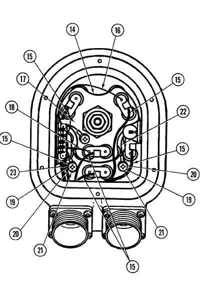
Refer to schematic (p6-26) for identification of electrical
leads.
Unsolder six electrical leads (15) to CR-1 thru CR-6 at CR terminals.
Unsolder electrical lead C-6 to CR-6 (16) at diode.
Unsolder electrical lead C-4 to CR-5 (17) at diode.
Unsolder electrical lead C-2 to CR-4 (18) at diode.
Remove two screws (19), two serrated washers (20) and two flat
washers (21) from heat sink (14), releasing electrical leads C-7 to E-2
(22) and C-2 to E-1 (23).