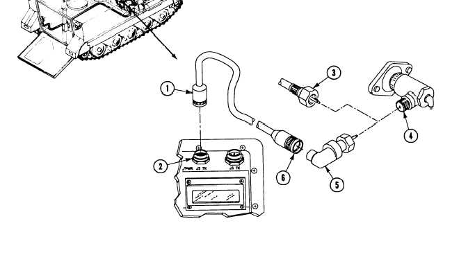
TM 9-2350-261-20-1H O O K U P / R E M O V E S T E / I C E - R F O R E N G I N E R P MINITIAL SETUPTools:References (cont):General Mechanic’s Tool Kit (Item 30, App D)TM 9-4910-571-12&PSTE/ICE-R Test Set (Item 71.1, App D)Equipment Conditions:Personnel Required:Engine stopped (see yourUnit MechanicCarrier blocked (see yourSTE/ICE-R power hooked up (page 3-275)References:Power plant rear access panel removedSee your -10(page 24-27 or 24-29)-10)-10)HOOK UP4.1.2.3.Remove transducer cable W4 and pulsetachometer from transit case.5.Pull VTM circuit breaker to OFF.Connect cable W4P1 (1) to jack J2 TK (2)on VTM.6.7.8.Disconnect tachometer cable (3) fromtachometer drive adapter (4) on engine(page 11-14).Install pulse tachometer (5) on tachometerdrive adapter (4).C A U T I O NTo prevent cable damage, make surecable is clear of belts and fan blade.Connect cable W4P2 (6) to pulsetachometer (5).Push VTM circuit breaker to ON.Return to troubleshooting.GO TO NEXT PAGEChange 13-277
Integrated Publishing, Inc. - A (SDVOSB) Service Disabled Veteran Owned Small Business