|
| |
TM 9-2350-287-34
3-2. ENGINE ASSEMBLY REPLACEMENT (continued).
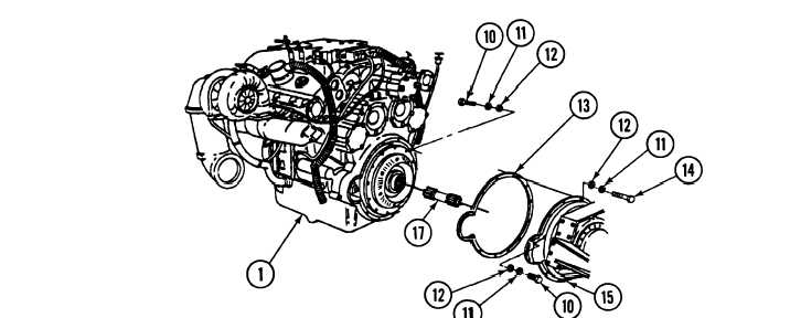
7.
Install shouldered shaft (17) in transfer assembly (15) so both internal and external splines mesh.
8.
Install new gasket (13) on engine (1). With the aid of an assistant, raise lifting device and connect engine (1)
to transfer assembly (15) with 14 washers (12) and new Iockwashers (11), nine screws (14), three screws (16),
and two screws (10). Torque screws (10, 14, and 16) between 60 and 70 ft-lb (81 and 95 N•m).
9.
10.
11.
With the aid of an assistant, install tie bar (5) on engine (1) with six washers (6), new Iockwashers (7), and
screws (8). Torque screws between 90 and 100 ft-lb (122 and 135 N•m).
Install tie bar (5) on transmission(9) with six washers (4), new Iockwashers (3), and screws (2). Torque screws
between 140 and 150 ft-lb(190 and 203 N•m).
Block engine (1) and remove sling. Detach lifting device from sling.
FOLLOW-ON MAINTENANCE:
Install vibration damper (para 3-4).
3-5
|