|
| |
TM 9-2350-287-34
5-2. COOLING FAN DRIVE ASSEMBLY REPAIR (continued).
19.
20.
21.
22.
23.
24.
25.
26.
27.
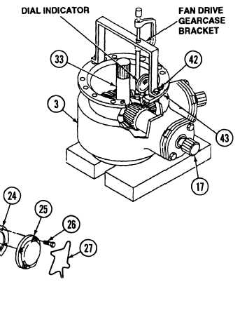
Set fan drive assembly (3) on wood blocks on a flat, level surface.
Aline fan drive gearcase bracket with holes in fan drive assembly (3) and secure with two screws (42) and nuts
(43).
Install dial indicator on fan drive gearcase bracket with plunger positioned on teeth of gear (32).
Hold drive shaft (33) secure to prevent any movement, and rotate gear shaft (17) fully counterclockwise (DO
NOT FORCE). Record backlash measurement.
l
l
l
NOTE
Backlash measurement between gear shaft and drive shaft must be between
0.002 and 0.004 inch.
If backlash measurement is less than 0.002 inch or greater than 0.004 inch, do
steps 23 through 27 to obtain required backlash.
If backlash measurement is OK, go to step 27.
Remove four screws (26), cover (25), and gasket (24) from fan drive assembly (3).
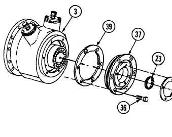
Remove retaining ring (35) from bearing (34).
Remove six screws (36) and housing cover (37) from fan drive assembly (3). Remove or add shims (39) from
fan drive assembly (3) as necessary.
Repeat steps 5,6, and 19 through 22.
Secure four screws (26) with new Iockwire (27).
5-10
|