|
| |
TM 9-2350-287-20-2
18-25. APU GROUND CABLES (11671369-1) REPLACEMENT (continued).
2.
3.
b.
1.
2.
3.
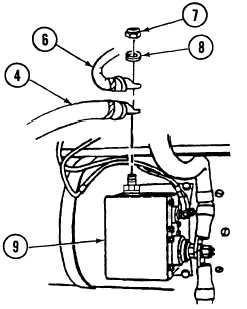
Remove self-locking nut (7) and Iockwasher (8) securing cable assembly 12329662 (6) and ground lead
11671369-1 (4) to generator relay box terminal E (9). Discard Iockwasher and self-locking nut.
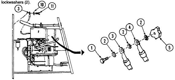
Remove screw (11 ), Iockwasher (10), and ground lead (3) from
Iockwasher.
INSTALLATION
rear wall of APU compartment.
Install ground lead (3) on rear wall of APU compartment with screw (11) and new Iockwasher (10).
Discard
Install ground lead 11671369-1 (4) and cable assembly 12329662 (6) on generator relay box terminal E (9)
with new Iockwasher (8) and self-locking nut (7).
Install ground lead (3) and ground lead 11671369-1 (4) on APU engine block (5) with screw (1) and three new
FOLLOW-ON MAINTENANCE:
. Connect battery ground cables (para 7-41).
. Install APU plenum (para 18-17).
18-64
|