Order this information in Print

Order this information on CD-ROM

Download in PDF Format


Click here to make tpub.com your Home Page

Page Title: IDLER WHEEL AND HUB REPLACEMENT (continued)
Back | Up | Next

Click here for a printable version

Google


Web
www.tpub.com

Home


Information Categories
.... Administration
Advancement
Aerographer
Automotive
Aviation
Combat
Construction
Diving
Draftsman
Engineering
Electronics
Food and Cooking
Math
Medical
Music
Nuclear Fundamentals
Photography
Religion
USMC
   
Products
  Educational CD-ROM's
Printed Manuals
Downloadable Books


TM 9-2350-287-20-2 
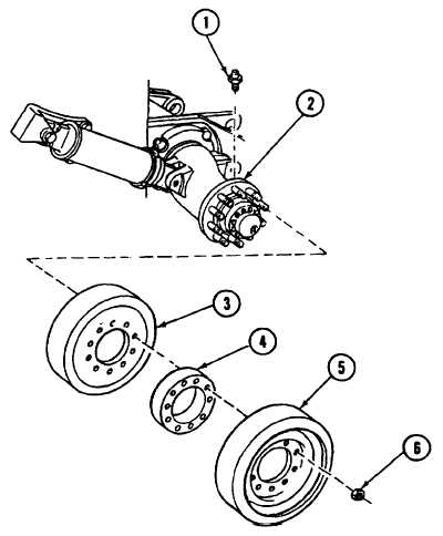
11-7.     IDLER WHEEL AND HUB REPLACEMENT (continued). 8. Install inner idler wheel (3), spacer (4), and outer idler wheel (5) on idler wheel hub (2). 9. Lubricate all threads with grease.  Install 10 new self-locking nuts (6) on outer idler wheel (5).  Torque nuts to 215 ft-lb (292 N m). 10. Static-test idler arm assembly (15) and idler wheel hub (2).  Idler arm assembly (15) must hold 50 5 psi (345   34 kPa) under static air pressure for one minute. 11. Install relief valve (1) on idler wheel hub (2). 12. Fill idler wheel hub (2) with grease until air-free fluid flows from relief valve (1). FOLLOW-ON MAINTENANCE:   Install track (para 11-14). Change 1  11-19

Privacy Statement - Press Release - Copyright Information. - Contact Us - Support Integrated Publishing

Integrated Publishing, Inc. - A (SDVOSB) Service Disabled Veteran Owned Small Business