|
| |
17-28. HYDRAULIC CONTROL PANEL ASSEMBLY REPAIR (continued).
41.
42.
43.
44.
45.
46.
47.
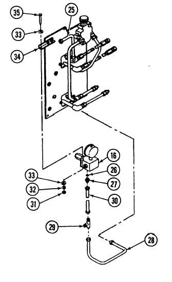
Install pressure gage assembly (16) on
pressure gage bracket (34).
Install two screws (35), four washers (33), and
two new Iockwashers (32) and nuts (31) on
pressure gage assembly (16).
Tighten connectors of tube (25).
Install new packing (26) and adapter (27) on
pressure gage assembly (16).
Install tube assembly (30) on adapter (27).
Install tee tube (29) on tube assembly (30).
Install tube assembly (28) on tee tube (29) and
hydraulic control panel assembly (1).
e.
lNSTALLATION
NOTE
Apply Teflon pipe sealant to all male pipe threads prior to installation.
1.
Install hydraulic control panel assembly (1) on vehicle.
2.
Install three new bckwashers (21) and three screws (20) on hydraulic control panel assembly(1).
3.
Connect two ballistic shield hydraulic lines (15) to two hoses (24).
4.
Connect two conveyor hydraulic lines (22) to two tube assemblies (23).
5.
Connect hydraulic reservoir return line (18) to tube assembly (19).
6.
Connect hydraulic fluid inlet line (17) to pressure gage assembly (16).
17-92
TM 9-2350-287-20-2
|