|
| |
TM 9-2350-287-20-2
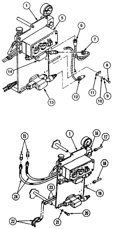
17-28. HYDRAULIC CONTROL PANEL ASSEMBLY REPAIR (continued).
2.
Remove
two
screws
(8),
washers
(10),
lockwashers (9), and straps (11) from hydraulic
control
panel
assembly
(1).
Discard
lockwashers.
3.
Remove electrical connector (7) from ballistic
shield solenoid valve (14).
4.
Disconnect electrical connector (12) from
conveyor solenoid valve (13).
5.
Disconnect
electrical
connector
(6)
from
hydraulic gage panel (5).
6.
Place drain pan under control valve to catch
hydraulic fluid.
7.
Disconnect hydraulic fluid inlet line (17) from
pressure gage assembly (16).
8.
Disconnect hydraulic reservoir return line (18)
from tube assembly (19).
9.
Disconnect two conveyor hydraulic lines (22)
from two tube assemblies (23).
10.
Disconnect two ballistic shield hydraulic lines
(15) from two hoses (24).
11.
Remove three screws (20) and lockwashers
(21) and hydraulic control panel assembly (1)
from vehicle. Discard lockwashers.
b.
DISASSEMBLY
NOTE
During
disassembly,
tag
all
hydraulic
components
for
identification during assembly.
1.
Remove tube assembly (28) from tee tube (29)
and hydraulic control panel assembly (1).
2.
Remove tee tube (29) from tube assembly (30).
Change 1 17-82
|