|
| |
TM 9-2350-287-20-2
15-50. MACHINE GUN SUPPORT ASSEMBLY REPAIR (continued).
d.
1.
2.
3.
4.
5.
6.
7.
8.
e.
ASSEMBLY
Install new spring pin (15) in support (6).
Install two new spring pins (8) in support (6).
Install lock (9) on right side of support (6). Position spring pin (15) to engage slotted end of lock (9). Anchor
spring (5) on spring pin (15).
Check travel of lock (9). Spring (5) should cause lock (9) to partially close hole in support (6). One-finger
pressure should rotate lock (9) to open hole in support (6); but if lock does not rotate easily, remove spring
(5) from spring pin (15) and lock (9). Back off spring (5) one full turn, then install spring (5) on lock (9) and
.
spring pin (15).
Install cover (16) on spring (5) with new cotter pin (4).
Install two S-hooks (11), chain (14), and quick-release pin (13) on connecting link (12).
Install connecting link (12) on support (6) with straight pin (1 O).
Install two new cotter pins (7) in straight pin (1 O).
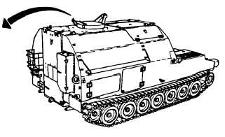
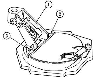
INSTALLATION
With the aid of an assistant, install support assembly (1) on commander’s cupola (2) with six screws (3).
FOLLOW-ON MAINTENANCE:
• None
15-127
|