|
| |
TM 9-2350-287-20-2
15-49. COMMANDER’S CUPOLA LOCKRING SAFETY HANDLE REPLACEMENT
This Task Covers:
a.
Removal
b.
Installation
Initial Setup:
Tools/Test Equipment:
Equipment Conditions:
General mechanic's tool kit (Item 24,
Vehicle parked on level ground (refer to
Appendix I)
TM 9-2350-287-10).
Lower rear door opened and secured (refer to
Materials/Parts:
TM 9-2350-287-10).
Self-locking bolt (2) (Item 302, Appendix H)
Upper rear door opened and secured (refer to
TM 9-2350-287-10).
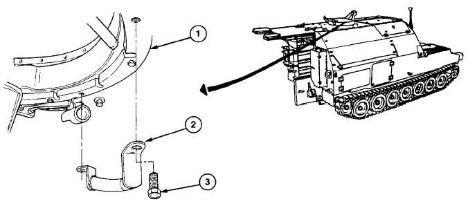
NOTE
The commander's cupola has two lockring safety handles. Only one is shown, but they are
replaced the same way.
a.
REMOVAL
Remove two self-locking bolts (3) and safety handle (2) from lockring (1). Discard self-locking bolts.
b.
INSTALLATION
Install two new self-locking bolts (3) and safety handle (2) on lockring (1).
FOLLOW-ON MAINTENANCE:
Close upper rear door (refer to TM 9-2350-287-10).
Close lower rear door (refer to TM 9-2350-287-10).
Change 1 15-124
|