TM 9-2350-287-20-1
7-48. DIODE HARNESS ASSEMBLY (12268417) REPLACEMENT.
This Task Covers
a. Removal
b. Installation
Initial Setup:
Tools/Test Equipment:
•General mechanic’s tool kit (Item 24,
Appendix I)
Equipment Conditions:
• Vehicle parked on level ground (refer to
TM 9-2350-287-10).
a.
REMOVAL
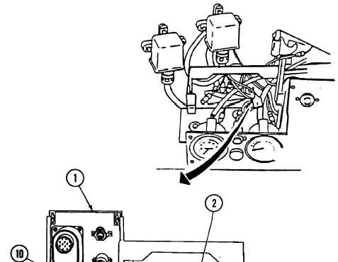
1.
Disconnect wire connector No. 14
(9) from starter switch (10) on back
of driver’s instrument panel (1).
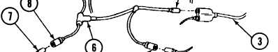
2.
Disconnect wire connector No. 27B
(5) from wire connector No. 27B
(4).
3.
Disconnect wire connector No. 27B
(2) from Y-connector (3).
4.
Disconnect wire connector No. 14
(8) from wire connector No. 14 (7).
• MASTER switch set to OFF (refer to
TM 9-2350-287-10).
• Battery ground cables disconnected (para 7-41).
• Drivet’s portable instrument panel
removed (para 7-6).
5.
7-141
Remove diode harness assembly
No. 12268417 (6) from vehicle.