TM 9-2350-287-20-1
7-21. MASTER RELAY BOX REPLACEMENT.
This Task Covers:
a. Removal
b. Installation
Initial Setup:
Tools/Test Equipment:
l General mechanic’s tool kit (Item 24,
Appendix I)
Materials/Parts:
l Lockwasher (2) (Item 130, Appendix H)
Equipment Conditions:
l Vehicle parked on level ground (refer to
TM 9-2350-287-10).
l MASTER switch set to OFF (refer to
TM 9-2350-287-10).
l Transmission access door opened
(refer to TM 9-2350-287-10).
l Battery ground leads disconnected
(para 7-41).
a.
1.
2.
b.
1.
2.
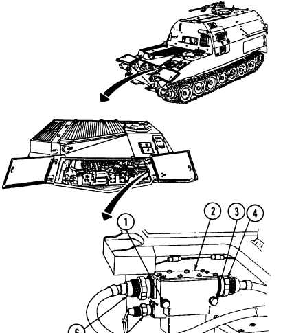
REMOVAL
Disconnect cable 82 (6), master
switch cable 459 (5), and battery
cable 81 (4) from master relay
box (2).
Remove two screws (1) and
Iockwashers (3) and master relay
box (2) from hull. Discard
Iockwashers.
INSTALLATION
Install master relay box (2) on
hull with two new Iockwashers
(3) and two screws (1).
Connect cable 82 (6), master
switch cable 459 (5), and battery
cable 81 (4) to master relay box
(2).
FOLLOW-ON MAINTENANCE:
l Connect battery ground cables (para 7-41).
l Close transmission access doors (refer to TM 9-2350-287-10).
7-65