TM 9-2350-287-20-1
2-19. TROUBLESHOOTING CHART (continued).
h. LIGHTS (continued).
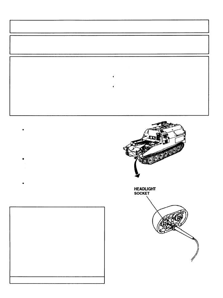
(10) ONE OR BOTH HEADLIGHTS FAIL TO OPERATE.
All other lights operate.
Initial Setup:
Tools/Test Equipment:
Equipment Conditions:
l Digital multimeter (DMM) (Item 13, Appendix I)
MASTER switch set to OFF (refer to TM
l General mechanic’s tool kit (Item 24,
9-2350-287-10).
Appendix I)
Lighting switch in SER DRIVE position
and dimmer switch set to low beam
Materials/Parts:
(refer to TM 9-2350-287-10).
l LockWasher (4) (Item 119, Appendix H)
Personnel Required: Two
NOTE
Instead of using multi meter
for voltage check, STE/lCE
troubleshooting,
INDIVIDUAL
BATTERY VOLATGE TEST-TEST
89 maybe performed.
l Instead of using multi meter
for continuity check, STE/lCE
troubleshooting, TEST 91 may
be performed.
l Troubleshooting procedures for both
headlight assemblies are identical.
If both headlights fail to work,
troubleshoot both according to steps
A through C.
A. 1. Remove four screws, Iockwashers, cover,
and headlight bulb from headlight assem-
bly. Discard Iockwashers.
2. Place red lead of multimeter in light bulb
socket and ground black lead.
3. Turn MASTER switch ON (refer to TM 9-
2350-287-10).
4. Turn MASTER switch OFF (refer toTM 9-
2350-287-10).
Is voltage indicated?
Continued on next page
2-166