TM 9-2350-287-10
LOCATION AND DESCRIPTION OF MAJOR COMPONENTS (continued)
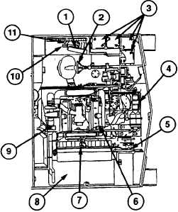
M992A1 Engine, Transmission, and Driver’s Compartments
DRIVER’S CONTROL SAND lNDlCATORS (1): Contained entirely in the driver's compartment.
STEERING CONTROLS, DRIVER’S (2): Allows driver to control vehicle direction.
BATTERIES (3): Four 12-volt lead-acid batteries connect to provide 24-volt vehicle electrical
s y s t e m .
TRANSMISSION (4): XTG-411-4 transmission contains cross-drive torque converter, four
speeds forward and two reverse.
FINAL DRIVE ASSEMBLIES (5): Transfer direct drive from transmission to drive sprockets.
MAIN ENGINE (6): Diesel, 8V71T, Low Heat Rejection/Cold Start (LHR/CS) engine provides
power to drive transmission.
COOLING FANS AND RADIATOR (7): Provide cooling to main engine.
FUEL TANKS, UPPER AND LOWER (8) (upper tank shown): Store fuel to power main engine
and the APU.
MAIN ENGINE EXHAUST SYSTEM (9): Expels exhaust gases from main engine.
LANYARD CABLE PULL HANDLE (10): Allows driver to manually discharge one engine
compartment fire extinguisher cylinder without leaving the vehicle.
FORWARD NATO SLAVE RECEPTACLE (11): Used to connect the M992A1 electrical
system with that of another vehicle for slave-starting operations; also used to provide power
access. Use only the forward receptacle when slave-starting another vehicle.
Change 1
1-7