TM 9-2350-277-34
REPAIR SHOCK ABSORBER
0039 00
THIS WORK PACKAGE COVERS:
Removal (page 0039 00-1).
Installation (page 0039 00-1).
INITIAL SETUP:
Maintenance Level
Direct Support
Tools and Special Tools
General Mechanic’s Tool Kit (WP 0120 00, Item 62)
Positioner (WP 0120 00, Item 42)
Arbor Press (WP 0120 00, Item 43)
Staker (WP 0120 00, Item 55)
Materials/Parts
Bearing (2)
Personnel Required
Track Vehicle Repairer 63H10
References
See your -20
Equipment Condition
Shock absorber removed (see your -20)
REMOVAL
1.
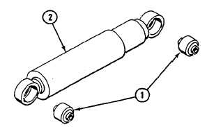
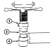
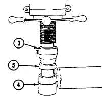
Remove two self-aligning bearings (1) from shock absorber (2). Use press (3), support (4), and positioner (5). Discard
bearings.
INSTALLATION
1.
Install two new self-aligning bearings (1) in shock absorber (2). Use press (3) and two positioners (5).
0039 00-1