TM 9-2350-277-20-3
REPLACE RAMP DOOR SWITCH AND MOUNT (M577A3 AND M1068A3 ONLY) —
Continued
0335 00
ADJUSTMENT
1.
Connect battery ground lead (WP 0338 00).
2.
Start engine (see your -10).
3.
Raise and lock ramp (see your -10).
4.
Stop engine (see your -10).
5.
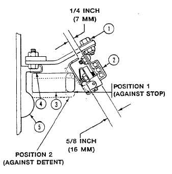
Loosen two screws (1) and slide switch (2) as far as possible from hull.
6.
Lock ramp door handle (3) against stop (4) (see Position 1 – Against Stop).
7.
Slide switch (2) against handle (3) to get approximately 1/4 inch (7 mm) clearance. Tighten screws (1).
8.
Move handle (3) against detent (5) (see Position 2 – Against Detent). Clearance should be approximately 5/8 inch
(16 mm).
9.
Check switch for proper operation. When handle (3) is in Position 2 (Against Detent), interior lights (white) should
come on and blue light should be off. When handle is in Position 1 (Against Stop) interior lights (white) should be off
and blue lights should be on. Repeat Steps 5 - 9 to make adjustments until switch operates correctly.
FOLLOW-THROUGH STEPS
1.
Turn MASTER SWITCH to ON (see your -10).
2.
Turn on dome lights and open ramp access door (see your -10). All dome lights should go off and blackout lights should
come on.
3.
Turn all switches OFF (see your -10).
4.
Turn MASTER SWITCH to OFF (see your -10).
END OF TASK
0335 00-4