TM 9-2350-277-20-2
REPLACE FUEL SUPPLY HOSES, TUBES, AND FITTINGS (M1064A3 ONLY) — Continued
0194 00
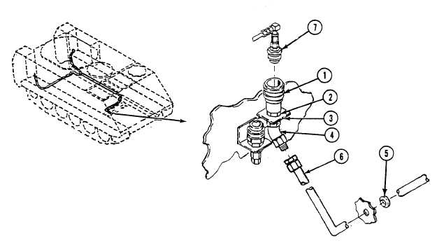
48. Install quick disconnect coupler body (1) and nut (2) in bracket (3).
49. Install elbow (4) on quick disconnect coupler body (1).
50. Install new grommet (5) on fuel supply hose (6). Route hose through hole in bulkhead and fit grommet into bulkhead.
51. Connect fuel supply hose (6) to elbow (4). Hold elbow when tightening hose.
52. Connect quick disconnect nose (7) to quick disconnect coupler body (1).
FOLLOW-THROUGH STEPS
1.
Fill fuel tanks (see your -10).
2.
Connect battery ground strap (WP 0337 00).
3.
Start engine (see your -10).
4.
Check for leaks in fuel lines.
5.
Stop engine (see your -10).
6.
Install power plant rear access panels (see your -10).
7.
Install rear floor plates (WP 0543 00).
8.
Install heater duct (WP 0706 00).
9.
Start engine (see your -10).
10. Raise and lock ramp (see your -10).
11. Stop engine (see your -10).
END OF TASK
0194 00-14

