TM 9-2350-277-20-1
NO EXTERIOR LIGHTS OPERATE
0029 00
INITIAL SETUP:
Maintenance Level
Unit
Tools and Special Tools
General Mechanic’s Tool Kit (WP 0926 00, Item 65)
Multimeter (WP 0926 00, Item 30)
Personnel Required
Unit Mechanic 63T10
References
See your -10
Equipment Condition
Engine stopped (see your -10)
Carrier blocked (see your -10)
T
1. Remove instrument panel for access. See task: remove
instrument panel mounts and ground lead (WP 0295 00).
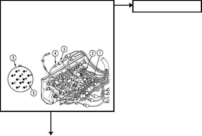
2. Remove harness 12349881 plug (1) from lighting control switch
(2).
3. Remove harness 12349881 circuit 15 plug (3) from harness
10933038 circuit 15 jack (4).
4. Measure resistance between harness 12349881 circuit 15 plug (3)
and lighting control switch plug (1) pin F (5).
5. Does multimeter read 0 ohms?
YES
NO
TN
1. Repair circuit 15 (WP 0382 00).
2. Verify no faults found.
0029 00-1