WIRE
A
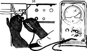
Disconnect wire 10 at accessory control box. Place MASTER
switch ON. Place red lead of multimeter on wire 10 socket in
connector. If voltage is not present, repair or replace wire 10
(p 6-77). If voltage is present, reconnect wire 10 to accessory
control box and go to step B.
B
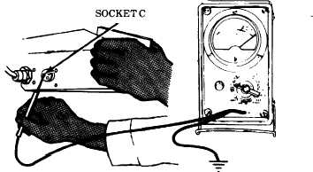
Disconnect wiring harness at accessory control box. Place
MASTER switch ON, HEATER SELECTOR switch LOW.
Place red lead of multimeter in socket C (wire 402) of accessory
control box and black lead to ground. If voltage is not present,
go to step D. If voltage is present, go to step C.
TA310532
2-173
TM 9-2350-267-20