TM 9-2350-267-10
OPERATING COMMUNICATION EQUIPMENT - Continued
Positions of CVC Helmet (4)
1.
2.
3.
4.
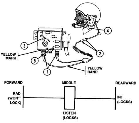
Connect CVC helmet cable connectors (1) to control box receptacles. Cable
with yellow band (longer cable) connects to receptacle with yellow mark.
Check that bail-out connectors (2) are snapped in place.
During operation, adjust VOLUME knob (5) for best reception.
Monitor switch (3) can beat A, ALL, or INT ONLY.
Talk to other crew members by pushing helmet switch (4) rearward. Set to
middle position when finished.
2-196