TM 9-2350-261-20-1
S T E / I C E I N D I V I D U A L B A T T E R Y T E S T C A RD
The BATTERY INTERNAL RESISTANCE TEST (73 or 77) evaluates the state of charge of an individual battery The BATTERY RESISTANCE
CHANGE TEST (75 or 79) evaluates whether the batteryIS good or bad, even if It is discharged A good battery thatIS discharged bay be recharged A
bad battery may hold a charge for a short time
STE/lCE HOOKUP
1.
The power to operate the STE/lCE VTM maybe taken from the batteries being tested as shown In the appropriate figure below or from an alternate
power source (such as another vehicle’s batteries).
2.
Perform VTM general setup, run confidence test and enter vehicle If)
3.
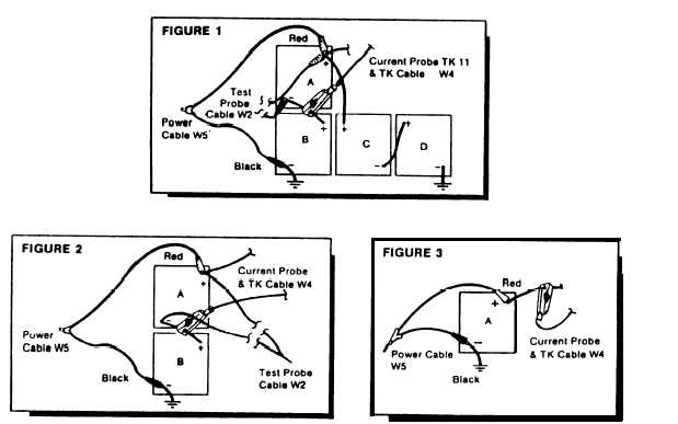
If there IS more than one battery in the vehicle/equipment, then find the battery series pair that includes the battery under test A battery series pair is
a pair of batteries for which the negative terminal of one battery is connected by a cable to the positive terminal of another battery. For example, In
figure 1 and 2 below, batteries A a nd B area series pair, and in figure 1 below, batteries C and D are a series pair,
4a.
If the vehicle/equipment under test has more than one battery or If the VTM IS powered from an alternate power source, then use tests 77 and
79 Connect the red clip of test probe cable W2 to the positive terminal of the battery under test. Connect the black clip of test probe cable W2
10 the negative terminal of the battery under test
b.
If the vehicle/equipment under test has only one battery which IS also supplying power to the VTM. use tests 73 and 75. The test probe cable
W2 IS not used.
5a.
If the vehicle/equipment under test has more than one batter, then the battery under testIS part of a series pair of batteries. Clamp the
current probe around the cable connecting the series pair. point the arrow on the current probe along the cable Ieadlng towards the
negative terminal as shown in figures 1 and 2
b.
If the vehicle/equipment under test has only one battery, then clamp the current probe around the positive battery cable connected to the
starter Point the arrow on the current probe along the cable in the direction Ieading towards the starter as shown in figure 3.
TEST PROCEDURE
1
2
3
4
Condition the current probe before running these tests
Measure the battery resistance change by entering test number 75 or 79 (as described In the hookup procedure) Then engage the starter for about
5 seconds
Measure the battery Internal resistance by entering test number 73 or 77 (as described in the hookup procedure) Then engage the starter
for about 5 seconds,
Compare the results of both measurements to Iimits In the vehicle/equipment TM or to limits on the reverse side of this card
If either measurement iS outside of normal limits, check battery terminals and connections, and check battery electrolyte level Then perform both
measurements a second time.
If the battery resistance change lest (75 or 79) falls after the second measurement, then the batteryIS in bad condition The battery may be able to
accept and hold a charge, but it wiII quickly become discharged during use. A battery in bad condition should be replaced
If the battery internal resistance test (73 or 77) fails after the second measurement, then the battery should be recharged.
3-254
Change 1