Home
Download PDF
Order CD-ROM
Order in Print
P H O N E E X T E N S I O N B O X A 1 4 P O S T ( S ) I N O P E R A T I V E ...CONT. - TM-9-2350-261-20-1_570
S P E E D O M E T E R M A L F U N C T I O N S
TM-9-2350-261-20-1 Carrier Personnel Full Tracked Armored M113A2 2350-01-068-4077 Carrier Command Post Light Tracked M577A2 2350-01-068-4089 Manual
Page Navigation
536
537
538
539
540
541
542
543
544
545
546
TM 9-2350-261-20-1
1.
2.
3.
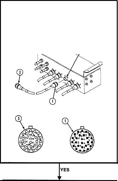
Remove cable W32 plug P107 (1) from jack J138 (2) on
Patch Panel Box A10.
Measure
resistance
between socket A of plug P7 (3) and
pin A of plug P107 (1). Repeat for socket/pins B
through a.
Does
multimeter
read 0 ohms for each measurement?
1. Replace Patch Panel Box A10 (page 40.1-21).
2. Verify no faults found.
1. Replace cable W32
(page 40.1-78).
2. Verify no faults found.
Change 3
3-226.136
Integrated Publishing, Inc. - A (SDVOSB) Service Disabled Veteran Owned Small Business