|
| |
TM 9-2350-287-34
9-4. PROJECTILE RACK SECTION REPAIR.
This Task Covers:
a. Disassembly
b. Assembly
b. Cleaning and Inspection
c. Test
Initial Setup:
Tools/Test Equipment:
• Lockwasher (2) (Item 67, Appendix H)
• Force gage (Item 18, Appendix D)
• Lockwasher (2) (Item 56, Appendix H)
• General mechanic’s tool kiti (Item 19,
• Lockwire (4) (Item 71, Appendix H)
Appendix D)
• Mounting rod (2 ) (Item 72, Appendix H)
• Projectile rack section test stand (Appendix E)
• Self-locking nut (2) (Item 121, Appendix H)
(fabricated)
• Projectile with inert fuse (Item 27, Appendix D)
Personnel Required: Two
• Wire twisting pliers (Item 48, Appendix D)
Equipment Conditions:
Material/Parts:
• Projectile rack assembly on clean work
• Cotter pin (9) (Item 4, Appendix H)
surface (refer to TM 9-2350-287-20-2).
a.
DISASSEMBLY
NOTE
Handles must be in release position before starling disassembly.
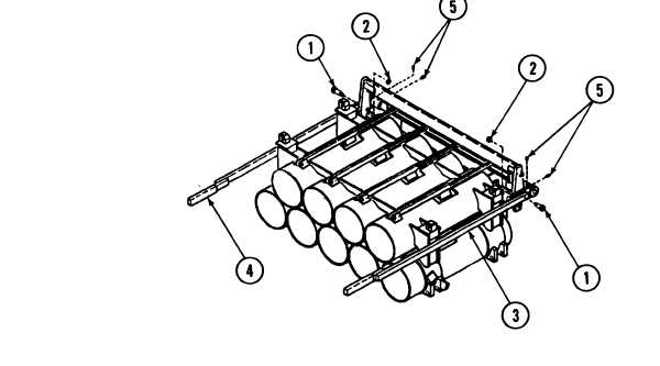
1.
Remove screw (1) and self-locking nut (2) from right locking handle (3) and left locking handle (4). Discard
self-locking nuts (2).
2.
Loosen two setscrews (5) on right locking handle (3) and left locking handle (4).
3.
Remove right
locking handle (3) and left Iocking handle (4).
9-13
|