|
| |
18-27. APU CABLE ASSEMBLY (11671380-2) REPLACEMENT.
This Task Covers:
a. Removal
b. Installation
Initial Setup:
Tools/Test Equipment:
. General mechanic’s tool kit (Item 24,
Appendix I)
Materials/Parts:
. Sealant adhesive (Item 6, Appendix D)
. Lockwasher (2) (Item 125, Appendix H)
. Lockwasher (Item 188, Appendix H)
Equipment Conditions:
. Vehicle parked on level ground (refer to
TM 9-2350-287-10).
a.
REMOVAL
1.
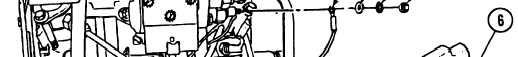
Remove engine cylinder shroud door panel (6) from APU.
2.
Remove nut (5), Iockwasher (4), and washer (3) securing lead assembly circuit R (2) to manifold heater (1).
Discard Iockwasher.
. MASTER switch set to OFF (refer to
TM 9-2350-287-10).
. Battery ground cables disconnected
(para 7-41).
. Left projectile rack assembly removed
(para 15-83).
. APU access plate removed (para 15-39).
18-67
TM 9-2350-287-20-2
|