|
| |
TM 9-2350-287-20-2
11-7. IDLER WHEEL AND HUB REPLACEMENT.
This Task Covers:
a. Removal
b. Installation
Initial Setup:
Tools/Test Equipment:
• Rag (Item 56, Appendix D)
l General mechanic’s tool kit
l Cotter pin (Item 40, Appendix H)
(Item 24, Appendix I)
• Self-locking nut (10) (Item 310, Appendix H)
l Torque wrench, 0 to 175 ft-lb
(Item 69, Appendix I)
Equipment Conditions:
• Torque wrench, 0 to 600 ft-lb
• Vehicle parked on level ground (refer to
(Item 70, Appendix I)
TM 9-2350-287-10).
l Track removed (para 11-14).
Materials/Parts:
l Grease (Item 33, Appendix D)
a.
1.
2.
3.
4.
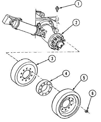
REMOVAL
Remove 10 self-locking nuts (6) from outer idler wheel (5). Discard self-locking nuts.
NOTES
Replacement of the left-side and right-side idler wheel and hub is the same. Left side
is shown here.
Remove outer idler wheel (5), spacer
(4), and inner idler wheel (3) from
idler wheel hub (2).
Remove relief valve (1) from idler
wheel hub (2).
Remove grease fitting (13) from cap
(10).
11-17
|