|
| |
TM 9-2350-287-20-2
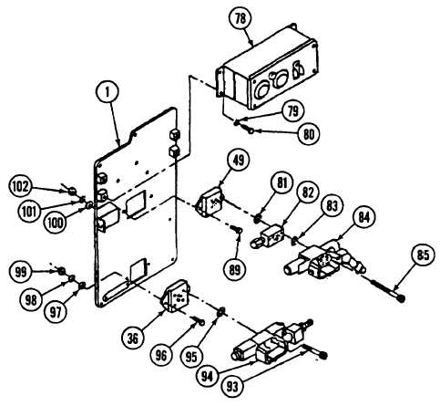
17-28. HYDRAULIC CONTROL PANEL ASSEMBLY REPAIR (continued).
39.
Remove four screws (80) and lockwashers (79) from gage panel assembly (78). Discard lockwashers.
40.
Remove gage panel assembly (78) from hydraulic control panel assembly (1).
41.
[Step Deleted]
42.
Remove four screws (93) and conveyor directional control valve (94) from hydraulic subplate (36). Remove and
discard two packings (95).
43.
Remove two screws (96), washers (97), lockwashers (98), and nuts (99) and hydraulic subplate (36) from
hydraulic control panel assembly (1). Discard lockwashers.
44.
[Step Deleted]
45.
Remove four screws (85), ballistic shield directional control valve (84), and subplate relief valve assembly (82)
from hydraulic subplate (49). Remove and discard two packings (81 and 83).
46.
Remove two screws (89), washers (100), lockwashers (101), and nuts (102) and hydraulic subplate (49) from
hydraulic control panel assembly (1). Discard lockwashers.
Change 1 17-86
|