|
| |
TM 9-2350-287-20-2
17-20. HYDRAULIC RESERVOIR REPAIR.
This Task Covers:
a. Removal
b. Disassembly
c. Cleaning and Inspection
d. Assembly
e. Installation
Initial Setup:
Tools/Test Equipment:
Lockwasher (6) (Item 161, Appendix H)
General mechanic's tool kit (Item 24,
Lockwasher (18) (Item 164, Appendix H)
Appendix I)
Lockwasher (5) (Item 196, Appendix H)
Drain pan (Item 14, Appendix I)
Nipple (Item 205, Appendix H)
Materials/Parts:
Personnel Required: Two
Cap and plug set (Item 13, Appendix D)
Dry-cleaning solvent (Item 28, Appendix D)
Equipment Conditions:
Rag (Item 56, Appendix D)
Vehicle parked on level ground (refer to
Teflon pipe sealant (Item 63, Appendix D)
TM 9-2350-287-10).
Filter and cap assembly (Item 41, Appendix H)
Hydraulic system pressure relieved to 0 psi
Gasket (Item 60, Appendix H)
(refer to TM 9-2350-297-10).
Gasket (Item 77, Appendix H)
Right projectile rack assembly moved to
Gasket (Item 84, Appendix H)
rear (refer to TM 9-2350-287-10).
APU plenum removed (para 18-17).
a.
REMOVAL
WARNING
To avoid possible injury, make sure all systems are shut down and MASTER
switch is set to OFF. Hydraulic fluid may be hot and can cause bums.
CAUTION
To prevent contamination of hydraulic system, cap hydraulic lines and ports
immediately after disconnection.
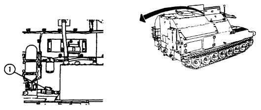
1.
Close ball valve (1).
Change 1 17-49
|