|
| |
TM 9-2350-287-20-2
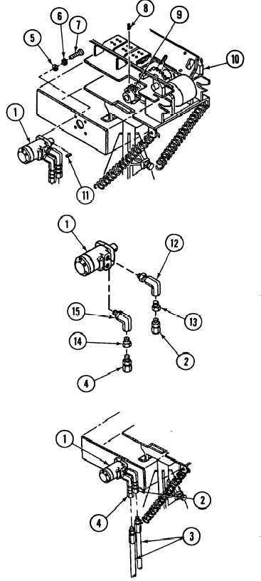
17-19. HYDRAULIC MOTOR REPLACEMENT (continued).
3.
4.
5.
b.
1.
2.
3.
4.
5.
6.
Loosen setscrew (8) in coupling
sprocket (9).
Remove four screws (7), Iockwashers
(6), and washers (5) and hydraulic
motor (1) from conveyor drive-end
section (10) and coupling sprocket
(9). Discard Iockwashers.
Remove key (11) from shaft of
hydraulic motor (1).
Remove two adapters (2 and 4),
reducers (13 and 14), and elbows (12
and 15) from hydraulic motor (1).
INSTALLATION
Install two elbows (12 and 15),
reducers (13 and 14), and adapters (2
and 4) on hydraulic motor (1).
Install key (11) in shaft of hydraulic
motor (1).
Aline key (11) in shaft of hydraulic
motor (1) with keyway in coupling
sprocket (9).
Install hydraulic motor (1) on conveyor
drive-end section (10) and coupling
sprocket (9) with four washers (5),
new Iockwashers (6), and screws (7).
Tighten setscrew (8) in coupling
sprocket (9).
Connect two hydraulic hoses (3) to
two adapters (2 and 4) on hydraulic
motor (1).
FOLLOW-ON MAINTENANCE:
l Stow conveyor (refer to TM 9-2350-
287-10).
l Open hydraulic ball valve (refer to TM
9-2350-287-10).
17-48
|