|
| |
17-14. DRIVE-END SECTION COUPLING SPROCKET, PILLOW BLOCKS, AND DRIVE
SPROCKET ASSEMBLY REPLACEMENT (continued).
2.
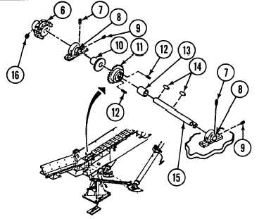
Loosen two setscrews (7) and setscrews
(9) in two pillow blocks (8) and setscrew
(16) in sprocket assembly (6), and remove
two setscrews (12) from sprocket
assembly (11).
3.
Using driftpin, drive shaft (15) from
sprocket assembly (6) side through
sprocket assembly (6), two pillow blocks
(8), spacer (13), sprocket assembly (11),
and spacer (10), then remove shaft (15)
from conveyor drive-end section (3).
4.
Remove sprocket assembly (6), spacer
(10), sprocket assembly (11), and spacer
(13) from conveyor drive-end section (3).
5.
Remove two keys (14) from shaft (15).
NOTE
To ensure proper installation, record the number and thickness of shims.
6.
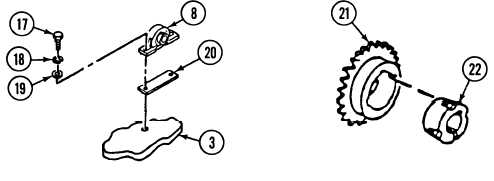
Remove four screws (17), Iockwashers (18), and washers (19), two pillow blocks (8), and shims (20) from
conveyor drive-end section (3). Discard Iockwashers.
7.
Remove sprocket (21) from hub (22).
b.
INSTALLATION
1.
Install sprocket (21) on hub (22).
2.
Install two pillow blocks (8) and shims (20) on conveyor drive-end section (3) with four washers (19), new
Iockwashers (18), and screws (17).
3.
Install shaft (15) through one of two pillow blocks (8). While driving in shaft (15), install spacer (13), key (14),
sprocket assembly(11), and spacer (10) on shaft (15) between two pillow blocks (8).
17-33
TM 9-2350-287-20-2
|