|
| |
TM 9-2350-287-20-2
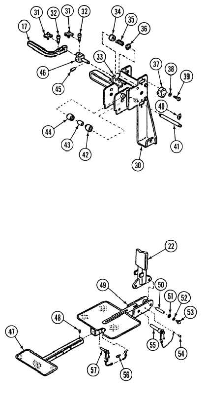
15-63. COMMANDER’S SEAT REPAIR (continued).
7.
8.
9.
10.
11.
12.
13.
14.
15.
Remove four washers (40) from two
shafts (41 ) on front of manual control
lever (30). Slide both shafts (41 ) out of
manual control lever (30). Remove four
bearings (42 and 44) and two spacers
(43) from manual control lever (30).
Remove eight screws (39) and
Iockwashers (38) and four roller
assemblies (37) from manual control
lever (30). Discard Iockwashers.
Remove two washers (31 ) and headed
pins (32) and locking handle (17) from
pin assembly (46).
Drive out grooved pin (45) and remove
pin assembly (46), washer (36), spring
(35), and sleeve (34) from pin housing
(33).
Remove screw (54) and quick-release
pin (55) from footrest assembly (49).
Remove two screws (53), Iockwashers
(52), and washers (51) and pin (50)
from footrest assembly (49). Discard
Iockwashers.
Remove footrest assembly (49) from
post (22).
Remove screw (56) and quick-release
pin (57) from footrest assembly (49).
Remove screw (48) and footrest
extension (47) from footrest assembly
(49).
15-159
|