TM 9-2350-287-20-1
7-61. DRIVER’S INSTRUMENT PANEL WIRING HARNESS (12268104) REPLACEMENT
(continued).
b.
1.
2.
3.
4.
5.
6.
7.
8.
9.
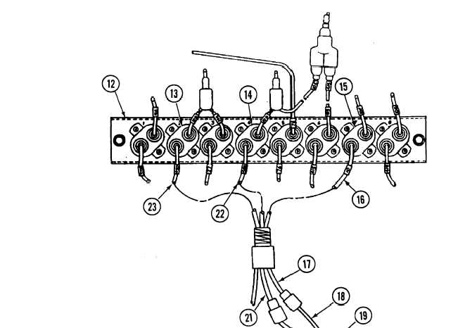
INSTALLATION
Connect lead No. 10 (16) to circuit breaker No. 7(15) on circuit breaker panel No. 1
Connect lead No. 588 (22) to circuit breaker No. 4 (14) on circuit breaker panel No.
Connect lead No. 450 (23) to circuit breaker No. 2 (13) on circuit breaker panel No.
(12).
1 (12).
1 (12).
Connect leads No. 459A and No. 509E (21 and 17) to leads No. 459A and No. 509E (20 and 18) of wiring
harness (19).
Connect lead No. 10(10) to bottom terminal of starter switch(11 ).
Connect lead No. 588 (8) to top terminal of fuel pump prime switch (9).
Connect lead No. 10 (6) to bottom terminal of glow plug switch (7).
Connect lead No. 450 (4) to bottom terminal of bilge pump switch (5).
Secure driver’s instrument panel (3) on mount (2) with six screws (1).
FOLLOW-ON MAINTENANCE:
Install driver’s portable instrument panel (para 7-6).
Connect battery ground cables (para 7-41).
7-192