TM 9-2350-287-20-1
2-19. TROUBLESHOOTING CHART (continued).
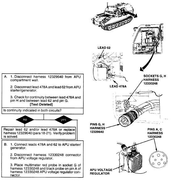
u. AUXILIARY POWER UNIT (continued).
(6) GENERATOR CHARGING SYSTEM INDICATOR
READS IN LOW YELLOW OR RED WITH MAIN
ENGINE CHARGING.
Initial Setup:
Tools/Test Equipment:
Personnel Required: Two
Digital multimeter (DMM) (Item 13, Appendix I)
General mechanic's tool kit (Item 24,
Equipment Conditions:
Appendix I)
APU plenum removed (para 18-17).
NOTE
·Instead of using multimeter for voltage
check, STE/ICE troubleshooting, INDIVIDUAL
BATTERY VOLTAGE TEST-TEST 89 may be
performed.
·Instead of using multimeter for continuity
check, STE/ICE troubleshooting, TEST 91
may be performed.
·Activate reset switch on APU voltage
regulator
prior
to
performing
troubleshooting, and test generator charging
system. If condition persists, perform
troubleshooting procedure.
·Check for APU hydraulic pressure between
100 and 300 psi. If pressure is not between
100 and 300 psi, adjust hydraulic flow
regulator. If condition persists, perform
troubleshooting procedure.
Continued on next page
Change 1 2-317