TM 9-2350-287-20-1
I
2-19. TROUBLESHOOTING CHART (continued).
I
Iu. AUXILIARY POWER UNIT (continued).
(1) ENGINE CRANKS BUT FAILS TO START
(continued).
CONTINUED FROM L
L. 5. Place multimeter lead on each connector of
FUEL SHUT-OFF switch.
6. Place FUEL SHUT-OFF switch in ON posi-
tion (refer to TM 9-2350-287-10).
7. Check for continuity.
Is continuity indicated?
I
I
1
Replace FUEL SHUT-OFF switch
(para 7-22). Verifyproblem is solved.
M. 1. Reconnect two leads to FUEL SHUT-OFF
switch.
2. Reconnect harness 12330248 to APU con-
trol box panel.
3. Install bracket and access panel on APU
control box with four new Iockwashers and
screws.
4. Install NBC air purifier (para 22-2).
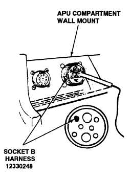
5. Place red probe of multimeter on socket B
of wall-mounted connector and ground black
probe.
6. With the aid of an assistants turn MASTER
switch ON (refer to TM 9-2350-287-10).
7. Turn FUEL SHUT-OFF switch ON (refer to
TM 9-2350-287-10).
8. Check for 24 ± 3 vdc.
9. Turn MASTER switch and fuel SHUT-OFF
switch OFF (refer to TM 9-2350-287-10).
Is voltage indicated?
Continued on next page
2-299