TM 9-2350-287-20-1
2-19. TROUBLESHOOTING CHART (continued).
I
HYDRAULIC SYSTEMS, ELECTRICAL (continued).
(1) UPPER REAR DOOR DOES NOT GO UP OR
DOWN (continued).
CONTINUED FROM E
E.
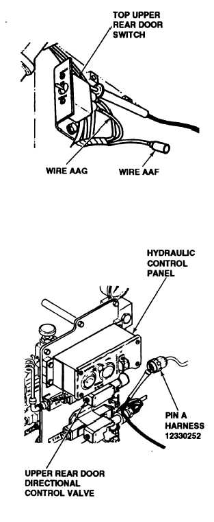
3. Place red lead of multimeter in top switch
connector and ground black lead.
4. Turn MASTER switch ON (refer to TM 9-
2350-287-10).
5. Place upper rear door switch in UP posi-
tion.
6. Check for 24 ± 3 vdc.
7. Place red lead of multimeter in bottom
switch connector and ground black lead.
8. Hold upper rear door switch in DOWN
position.
9. Check for 24 ± 3 vdc.
10. Turn MASTER switch OFF (refer to TM
9-2350-287-10).
Is voltage indicated at both circuits?
I
IReplace upper rear door switch (para 7-23).
Verify problem is solved.
F. 1. Reconnect wires AAF and AAG to upper
rear door switch.
2. Disconnect wire harness 12330252 con-
nector from upper rear door directional con-
trol valve on hydraulic control panel.
3. Place red lead of multimeter on pin A and
ground black lead.
4. Turn MASTER switch ON (refer to TM 9-
2350-287-10).
5. Hold upper rear door switch to the UP
position.
Continued on next page
2-284