TM 9-2350-287-20-1
2-19. TROUBLESHOOTING CHART (continued).
h. LIGHTS (continued).
(18) ACCESSORY CONTROL BOX PANEL LIGHTS
FAIL TO OPERATE. All other lights operate
(continued).
CONTINUED FROM A
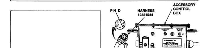
B.
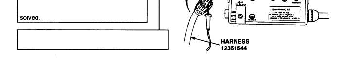
1. Disconnect harness 12351544 from ac-
cessory control box.
2. Place multimeter red lead in pin D of
harness 12351544 and ground black lead.
3. Turn MASTER switch ON (refer to TM 9-
2350-287-10).
4. Check for 24 ± 3 vdc.
5. Turn MASTER switch OFF (refer to TM 9-
2350-287-10).
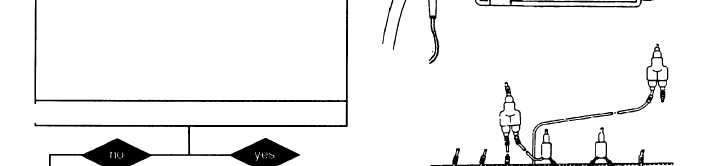
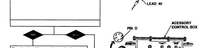
Is voltage indicated?
Repair or replace accessory control box
(para 7-10).
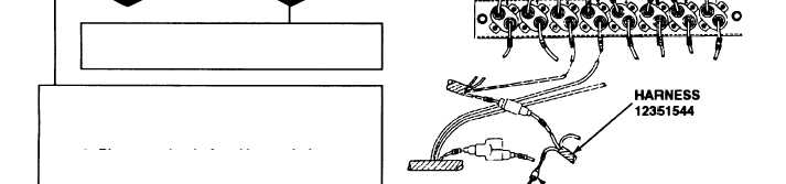
C.
1. Disconnect harness 12351544 lead 40
from “Y” connector.
2. Place one lead of multimeter in harness
12351544 lead 40 and place other lead on
socket D of harness 12351544 accessory
control box connector.
3. Check for continuity.
Is continuity indicated?
Repair wire 40 or replace wire harness
12351544 (para 7-64). Verify problem iS
D. 1. Connect wire harness 12351544 to acces-
sory control box.
Continued on next page
2-200