TM 9-2350-287-20-1
2-19. TROUBLESHOOTING CHART (continued).
e. AIR CLEANER FAN ASSEMBLY (continued).
(1) AIR CLEANER BLOWER MOTORS DO NOT
OPERATE WITH VEHICLE IN GEAR (continued).
CONTINUED FROM E
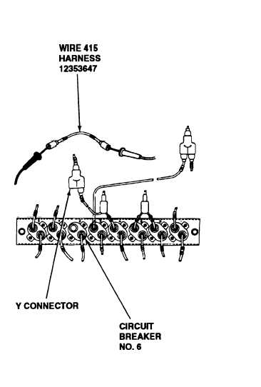
E. 3. Place red lead of muitimeter in wire 415 of
lead assembly 12353647.
4. Turn MASTER switch ON (refer to TM 9-
2350-287-10).
5. Check for 24 ± 3 vdc.
6. Turn MASTER switch OFF (refer to TM 9-
2350-287-10).
Is voltage indicated?
F. 1. Disconnect wire 415 of lead assembly
12353647 from Y connector.
2. Place one lead of multimeter in wire 415
circuit breaker connector and place other lead
of multimeter in wire 415 socket connector and
check wire 415 for continuity.
Is continuity indicated?
G.
1. Reconnect lead 12353647 (wire 415) to Y
connector and circuit breaker no. 6.
2. Disconnect wire 10E of harness 12376405
from Y connector.
3. Place multimeter red lead in wire 10E socket
and ground black lead.
Continued on next page
Replace circuit breaker no. 6
(para 7-11). Verify problem
is solved.
Replace lead assembly 12353647
(para 7-62). Verify problem is solved.
2-84