TM 9-2350-277-34
REPAIR POWER CONTROL ENCLOSURE, RIGHT PANEL (M1068A3 ONLY) — Continued
0092 00
3.
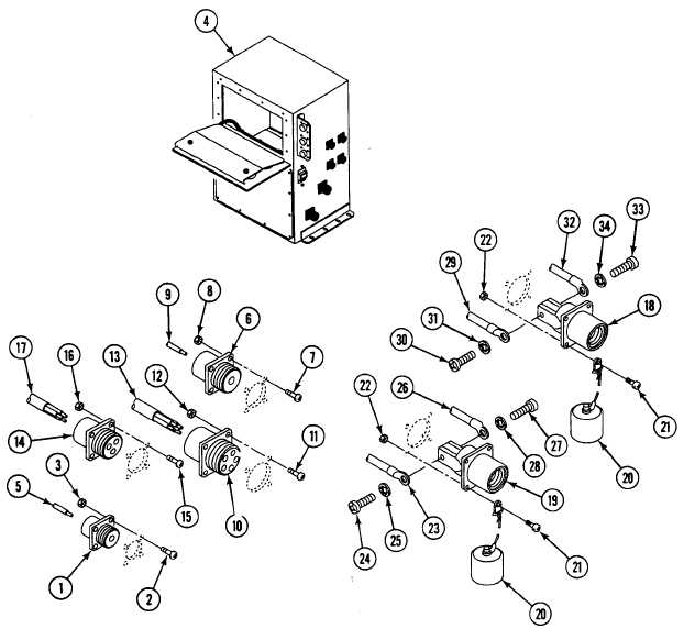
Install connector J29 (1), four screws (2), and new locknuts (3) on enclosure (4). Install circuit lead 34A (5) on J29 (1).
4.
Install connector J28 (6), four screws (7), and new locknuts (8) on enclosure (4). Install circuit lead 44A (9) on J28 (6).
5.
Install connector J27 (10), four screws (11), and new locknuts (12) on enclosure (4). Install circuit leads 11A, 28A, 12A,
28B, and 3W (13) on J27 (10).
6.
Install connector J37 (14), four screws (15), and new locknuts (16) on enclosure (4). Install circuit leads 20B, 18D, and
3AC (17) on J37 (14).
7.
Install connector J25 (18), connector J26 (19), two dust caps (20) with retainers, eight screws (21), and new locknuts
(22) on enclosure (4).
8.
Install circuit 32C lead (23), screw (24), and lockwasher (25) on negative terminal of connector J26 (19).
9.
Install circuit 36C lead (26), screw (27), and lockwasher (28) on positive terminal of connector J26 (19).
10. Install circuit 32E lead (29), screw (30), and lockwasher (31) on negative terminal of connector J25 (18).
11. Install circuit 31A lead (32), screw (33), and lockwasher (34) on positive terminal of connector J25 (18).
0092 00-7