TM 9-2350-277-20-6
REPAIR POWER CONTROL ENCLOSURE FACEPLATE AND BRACKET (M1068A3 ONLY)
— Continued
0828 00
NOTE
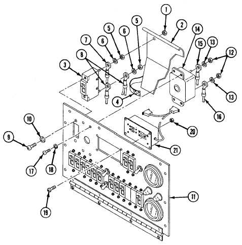
Tag all leads before removal.
There are 12 circuit breakers alike. All circuit breakers are removed in the same way. The art
work shows the removal of only one circuit breaker. Use wiring diagram in the back of the
manual.
5.
Remove nut (1) and safety cover (2) from terminal 1 of circuit breaker CB1 (3). Unwrap velcro strap (4) from around
local wiring.
6.
Remove two nuts (5) and lockwashers (6) from circuit breaker CB1 (3).
7.
Remove circuit 7A lead (7) from terminal 1 of circuit breaker CB1 (3).
8.
Remove circuits 9A, 9E, and 9D leads (8) from terminal 2 of circuit breaker CB1 (3).
9.
Remove two screws (9), lockwashers (10), and circuit breaker CB1 (3) from faceplate (11). Discard lockwashers.
10. Remove two nuts (12) and lockwashers (13) from circuit breaker CB2 (14).
0828 00-3