TM 9-2350-277-20-3
REPLACE/REPAIR DISTRIBUTION BOX (M981A3 ONLY) — Continued
0273 00
7.
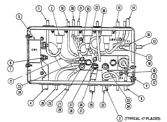
Route circuit 450B lead (1) through grommet (2) and into rear cover. Connect lead to circuit breaker CB3 (3).
8.
Route cable assembly W14 lead (4) through grommet and into rear cover. Connect lead to circuit breaker CB1 (5).
Install washer (6) and nut (7). TORQUE NUT TO 40 +/- 5 LB-IN. (4.5 +/- 0.6 N m).
9.
Route lead (8) through grommet and into rear cover. Connect lead (8) to block E2 (9). Install washer (10), new
lockwasher (11), and nut (12).
10. Route lead (13), cable assembly W15 lead (14), and cable assembly W12 lead (15) through grommets and into rear
cover. Connect leads to ground block E1 (16). Install washer (17) and nut (18).
11. Route circuit 14 lead (19) and cable assembly W8 lead (20) through grommets and into rear cover. Connect circuit
breaker CB3 lead (21), circuit 14 lead (19), and cable assembly W8 lead (20) to bus bar (22) as shown. Install washer
(23) and new locknut (24).
12. Route two VFM leads (25) and (26) through grommets and into rear cover. Connect leads to bus bar (22) and install
washer (27) and nut (28). TORQUE NUT TO 40 +/- 5 LB-IN. (4.5 +/- 0.6 N m).
13. Route circuit 49 lead (29) through grommet and into rear cover. Connect lead to bus bar (22). Install washer (30) and
nut (31).
NOTE
If circuit breaker CB2 lead (35) and circuit breaker CB5 lead (36) were disconnected during
removal, reconnect circuit breaker leads to bus bar (22) and install washer (37) and nut (38).
14. Route CKT 6A (32) through grommet and into rear cover. Connect lead to bus bar (22) and install washer (33) and
nut (34).
0273 00-16