12-16
Change 4
TM 9-2350-267-34
APU GEAR CASE: DISASSEMBLY, INSPECTION, REPAIR AND ASSEMBLY (Continued)
v
W
X
Y
Z
AA
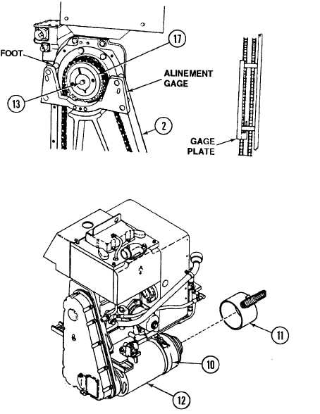
Install alinement gage (item 26, Appx D) with four feet flat against
machined section of chain housing (23).
Position gage plate between two rows of drive sprocket teeth. Gage
plate should fit just touching rear drive sprocket teeth.
NOTE
Prior to tightening screw (13), note position of sprocket
edge and bushing edge to aid in adjustment of sprocket.
With alinement gage in held position, torque screw (13) to 50-55 lb-
ft. Gage plate should not be touching either row of teeth at this point.
Repeat steps Wand X to aline sprocket (17) if necessary.
Install generator cooling air duct (11) on generator (12).
Tighten strap (10).