HOOK UP STE/lCE TEST EQUIPMENT ON BATTERIES (CONTINUED)
C
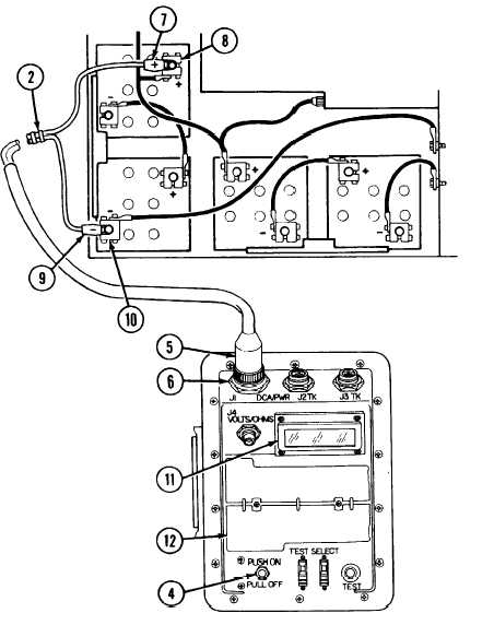
Install plug W5P1 (5) on VTM jack J1 (6).
D
Install red lead (7) of cable W5 (2) on battery positive terminal
clamp (8).
E
Install black lead (9) of cable W5 (2) on battery negative ter-
minal clamp (10).
F
Push VTM circuit breaker (4) to on.
1 If display (11) shows 8888, then ----, go to Step G.
2 If display (11) is not blank but does not show 8888 and ----,
write up DA form 2404 on faulty VTM display. Report pro-
blem to supervisor.
3 If display (11) is blank refer to TM 9-4910-571-12&P for
troubleshooting of STE/ICE
G Perform VTM confidence check. See operating instructions on
flip cards (12). If VTM confidence check fails, replace STE/ICE
H
Proceed to appropriate STE/ICE test.
TA312641
2-48.5
Change 1
TM 9-2350-267-20