TM 9-2350-261-34
INSTALL
12.
13.
14.
15.
16.
Install gearbox (1) on support (2). Secure
with four screws (3), eight washers (4), and
four nuts (5).
Install new packing (6), lockring (7), and
collar (8) on drive shaft (9). Use retaining
ring pliers.
Install bearing (10) in housing (11).
Install housing (11) and bearing (10) on
drive shaft (9) and collar (8) on bearing.
Position housing ( 11), bearing ( 10), and
collar (8) against lockring (7). Tighten
setscrew ( 12).
N O T E
Make sure two pins (13) are installed in
support (2) before doing step 17.
17. Install housing (11 ) and shaft (9) in
gearbox (1).
18. Secure housing (11) to support (2) with
three new key washers (14) and
screws (15).
19.
20.
21.
22.
23.
24.
25.
26.
Tighten three screws (15) to 252-300 in-lb
(28-34 N.m) torque. Use torque wrench
(item 117).
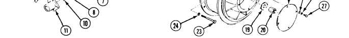
Install key (16) and fan (17) on shaft (18)
of gearbox (1). Secure with new washer (19)
and nut (20).
To set rotor and seal, tighten nut (20) to
70-75 lb-ft (95-102 N.m) torque. Then
loosen nut. Use torque wrench (item 112).
Apply sealing compound to both sides of
washer (19).
Tighten nut (20) to 324-384 in-lb
(37-43 N.m) torque. Use torque wrench
(item 117).
Bend one edge of washer (19) against
nut (20) and on edge against fan (17).
Install fan housing (21) on support (2).
Secure with six screws (22), two
screws (23), 16 flat washers (24), and eight
new locknuts (25).
Install cover (26) on fan housing (21).
Secure with four screws (27), new
lockwashers (28), and flat washers (29).
FOLLOW-THROUGH STEPS
1. Install fan assembly in carrier (see your –20).
END OF TASK
5-8
(1
-.\
x
-x
/
~.
(
----
-------
-
---’