TM 9-2350-261-20-2
REPLACE MASTER SWITCH ASSEMBLY
DESCRIPTION
This task covers:
Remove (page 9-13).
Install (page 9-14).
INITIAL SETUP
Tools:
References:
General Mechanics Tool Kit (Item 30, App D)
See your -10
Materials/Parts:
Lockwasher (3)
Self-locking nut (2)
Self-locking nut (8)
Equipment Conditions:
Engine stopped/shutdown (see your -10)
Carrier blocked (see your -10
Battery ground lead disconnected (page 13-2)
Personnel Required:
Unit Mechanic
REMOVE
NOTE
On M577A2 and M1068 carriers do step 3,
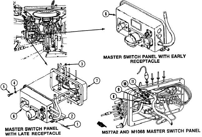
1. Disconnect circuit 37 lead (1) from connec-
tor (2).
then go to step 5. On all other carriers,
after step 2, go to step 4.
2.Remove eight locknuts (3), washers (4),
screws (5), and master switch panel (6) from
distribution box (7). Discard locknuts.
3. Remove nut (8), lockwasher (9), and circuit
49 lead (10) from master switch
terminal (11). Discard lockwasher.
GO TO NEXT PAGE
Change 3
9-13