TM 9-2350-261-20-2
INSTALL
N O T E
Steps 14 through 21 tell you how to install
the late model slave receptacles. Steps 22
through 27 tell you how to install the
early model slave receptacles.
Make sure protective cap retaining cord
is attached to receptacle lower mount
screw.
14.
15.
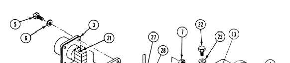
Install insulator (1), new gasket (2), and
auxiliary power receptacle (3) in master
switch panel (4). Secure with four screws
(5), washers (6), and new locknuts (7).
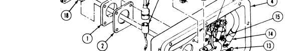
Install new grommet (8) on ground lead (9)
Route lead out of master switch panel (4).
Install grommet in panel.
16.
17.
18.
19.
20.
21.
Place ground lead (9) on instrument panel
strut hull mount. Secure with screw (10),
washer (11) and nut (12).
Install circuit 50 lead (13) and circuit 49
lead (14) on terminal of master switch (15).
Secure with washer (16) and nut (17).
Install ground lead (9) on negative post (18)
of auxiliary power receptacle (3). Secure
with screw (19) and new lockwasher (20).
Install circuit 50 lead (13) on positive post
(21) of auxiliary power receptacle (3). Secure
with screw (22) and new lockwasher (23).
Install master switch panel (4) on
distribution box. Secure with eight screws
(24), washers (25), and new locknuts (26).
Connect circuit 37 lead (27) to connec-
tor (28).
9-4