TM 9-2350-261-20-2
R E P L A C E I N S T R U M E N T P A N E L G A G E S
DESCRIPTION
This task covers:
Remove (page 11-11).
Install (page 11-12).
INITIAL SETUP
Tools:
References:
General Mechanics Tool Kit (Item 30, App D)
see your -10
Materials/Parts:
Equipment Conditions:
Lockwasher (2)
Engine stopped/shutdown (see your -10)
Carrier blocked (see your -10)
Personnel Required:
Battery ground lead disconnected (page 13-2)
Unit Mechanic
Instrument panel removed (page 11-2)
REMOVE
1.
2.
3.
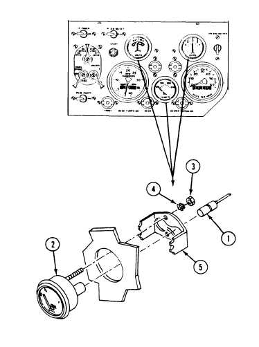
N O T E
There are three gages on the instrument
panel. Except for the number of leads,
remove all gages the same way.
Do not disconnect more than one gage at
a time. Mark each lead to make sure you
reconnect to correct contacts. See wiring
diagram (FO-2).
Disconnect circuit leads (1) from rear of
gage (2).
Remove two nuts (3), lockwashers (4), and
bracket (5) from rear of gage (2). Discard
lockwashers.
Remove gage (2) from front of instrument
panel.
GO TO NEXT PAGE
11-11