TM 9-2350-261-20-1
R E P L A C E F I L L E R C A P A N D S T R A I N E R P A R T S ( M 1 0 5 9 , M 1 1 3 A 2 ,
M 5 7 7 A 2 , M 1 0 6 8 , A N D M 9 0 1 A 1 O N L Y)
INITIAL SETUP
Tools:
General Mechanics Tool Kit (Item 30, App D)
Materials/Parts:
Non-electrical wire (Item 31, App C)
Gasket
Personnel Required:
Unit Mechanic
References:
See your -10
Equipment Conditions:
Engine stopped/shutdown (see your -10)
Carrier blocked (see your -10)
Battery ground lead disconnected (page 13-2)
Combat filler cover and lock open
(see your -10)
R E M O V E
1.
2.
3.
4.
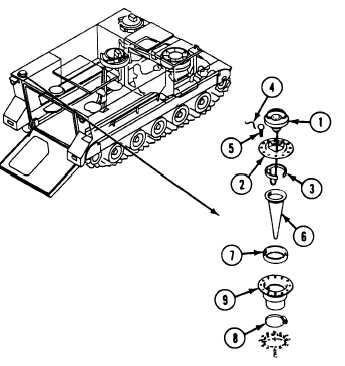
Unfasten fuel filler cap and chain assembly
(1) from filler neck (2).
Compress C ring (3) and remove from filler
neck (2).
Remove lockwire (4), 12 screws (5), filler neck
(2), strainer (6), retainer (7), and filler cap
and chain assembly (1) from hull top. Discard
lockwire.
Loosen clamp (8) that secures boot (9) to in-
7.
8.
9.
Install new lockwire (4) through heads of 12
screws (5). Secure with double twist method.
Compress C ring (3) and install through filler
neck (2).
Fasten filler cap and chain assembly (1) in
filler neck (2).
side fuel tank. Remove boot through top of
hull.
I N S T A L L
5.
6.
Aline mounting holes in boot (9) with mount-
ing holes in hull top. Secure boot (9) to inside
fuel tank neck with clamp (8).
Secure filler neck (2), retainer (7), strainer
(6), and filler cap and chain assembly (1) to
hull top with 12 screws (5).
F O L L O W - T H R O U G H S T E P S
1. Connect battery ground lead (page 13-2).
2. Combat filler cover closed and locked
(see your -10).
END OF TASK
6-8
Change 3