TM 9-2350-261-20-1
NOTE
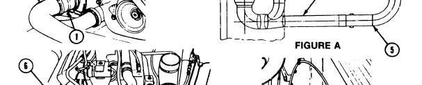
On carriers with exhausts as
Figure A, go to step 63.
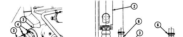
62. Install pipe joint (1) on muffler
63.
shown in
(2) and ex-
haust pipe (3). Secure with two clamps (4).
64.
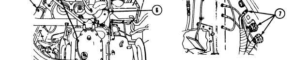
Install exhaust pipes (3 and 5) on engine
exhaust manifolds. Secure with two clamps
(6). Tighten clamps to 192-216 lb-in
(22-24 N•m) torque. Use torque wrench
(Mire 95) and socket wrench set.
Connect three electrical cables (7) at driver’s
compartment bulkhead.
FOLLOW-THROUGH STEPS
1.
2.
3.
4.
6.
6.
7.
Install air control valve and housing assembly
8. Start engine (see your -10). Check for leaks
(page 7-11).
and proper installation.
Open fuel supply valve at tank
(see- your -10).
9.
10.
Connect battery ground lead (page 13-2).
Lower grill (page 6-2).
11.
Fill cooling system (page 8-3).
12.
Adjust fuell control cutoff cable (page 23-44).
Check installation and operation of controls.
Stop/shutdown engine (see your -10).
Install power plant bottom access cover
(page 24-32).
Install power plant rear access panels
(page 24-27 or 24-29).
Install driver’s power plant access panel
(page 24-25).
END OF TASK
5-22